RISAConnection allows you to graphically view your connection in two- and three- dimensional views. Below, the functionality that is available within each of these views is explained.
To view the 3D view, simply click the 3D View tab in the Connection View. This view allow you to see the connection from all sides by simply clicking and dragging the mouse. All of the elements in the connection are drawn/modified in real time. Therefore, if you update a member size, or change the clip angle, you will see this update in the 3D View.

To view the 2D view, simply click the 2D View tab in the Connection View. This view allows you to use the tabs across the top of the screen to see the different connection components in various individual 2D Views. These dimensioned views allow you to double click the dimensions to show where this value is located in the Connection Properties. This makes it very easy to change a dimension or property in a 2D view. There are also some component views available simply for viewing the connection assemblies.
This view is available to show all of the output of the program. There are two main windows available: Members and Results (either LRFD or ASD, depending on the code chosen in Global Parameters). These reports are shown in real time. Therefore, whenever a property of the connection is changed, the program updates the result reports for this change.
The Members Report view shows detailed properties of all of the components in the connection. Tabs within the report allow you to switch between these components for member properties, hole dimensions, coping and material information.

In this example we have an end plate moment connection. Thus, we see tabs for each element in the connection, including the bolts for the connection. These are simply a presentation of properties of the connection. There are no engineering calculations used in these values.
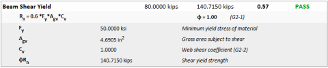
The Results Reports gives all of the design checks for the connection, as well as material properties for each component. These design checks are listed with the required strength, provided strength, unity check and whether the connection passed that specific check. A red FAILED message will clearly alert you if you have a connection check that is not passing. In addition to a list of unity checks for each connection you can also click on the individual check to get a detailed calculation complete with explanation of each variable in that check.
For more information/details on a specific design calculation, please see the specific check topic in the Help menu.
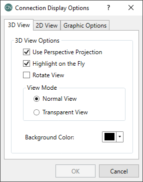
Plot Options settings provide both 2D and 3D viewing options as well as text size for the user interface and the printed reports.